
A Eurocode load combination is a set of design values for permanent and variable actions that are assumed to act together, so you can find the most adverse effect on a structure. In UK building design you take the rules from EN 1990 and its UK National Annex, and the action values from EN 1991. For ordinary STR checks you apply γG = 1.35 to unfavourable permanent actions and γQ = 1.50 to unfavourable variable actions. You reduce accompanying variable actions with ψ0, and you treat each variable action as the leading one in turn.
This guide sets out the expressions, the UK choices, a worked example with numbers, and the mistakes that cause rework at review.
TL;DR
- EN 1990 gives the combination rules. EN 1991 gives the actions (self-weight, imposed, snow, wind, temperature) that go into them.
- For UK building STR/GEO checks, the National Annex lets you use expression 6.10, or the less favourable of 6.10a and 6.10b.
- Typical UK factors for unfavourable actions: γG,sup = 1.35, γQ = 1.50. Accompanying variable actions are reduced by ψ0.
- Every variable action must take a turn as the leading action. The governing combination is the one with the worst effect.
- Accidental and seismic situations, serviceability and geotechnical checks each use their own combination sets.
Table of Contents
- What Eurocode load combinations are
- ULS and SLS combinations
- Expressions 6.10, 6.10a and 6.10b
- Worked example: one column, three actions
- Accidental, seismic and geotechnical cases
- National Annexes: what can and cannot change
- Common mistakes that cause rework
- A simple workflow for a combination schedule
- Our perspective on load combinations
- Get review-ready calculations without a permanent hire
- FAQ
- Sources
What Eurocode load combinations are
Structures rarely see one load at a time. Self-weight is always there, people and furniture come and go, and snow and wind arrive on their own schedules. A load combination states which of these you assume at the same time, and at what value, for a given check.
The framework is split across two parts. EN 1990 supplies the combination and reliability framework, while EN 1991 supplies the action models for permanent actions, variable actions and accidental situations. In a building ultimate limit state (ULS) combination you take the permanent actions, one leading variable action, and reduced accompanying variable actions. Then you repeat the exercise so that each plausible variable action leads once.
Where the actions come from
EN 1991-1-1 treats imposed building loads as variable free actions arising from occupancy, furniture, movable objects, vehicles and anticipated rare concentrations. It requires floor and roof areas to be given a use category and designed for a characteristic distributed load qk and a concentrated load Qk. The standard says qk is intended for general effects and Qk for local effects, so the two are checked separately and not added together.
Snow, wind and thermal actions come from the other parts of EN 1991 and their UK National Annexes. Your combination is only as good as the characteristic values you feed into it.
Design situations
EN 1990 recognises persistent, transient, accidental and seismic design situations. Persistent means normal use. Transient covers temporary conditions such as execution or alteration. Accidental covers exceptional events such as fire, impact or explosion. Seismic covers earthquake actions. Each has its own combination, which is why a single “1.35G + 1.5Q” rule is never the whole answer.
ULS and SLS combinations
Eurocode design checks whether design effects exceed resistance or serviceability criteria. The ultimate limit state categories are EQU (loss of equilibrium), STR (structural failure), GEO (ground failure) and FAT (fatigue), alongside the serviceability limit states.
In practice that gives you two families of combination:
| Check | What it protects against | Typical factors | Used for |
|---|---|---|---|
| ULS (STR/GEO) | Failure of members, connections or ground | γG = 1.35, γQ = 1.50, ψ0 on accompanying actions | Member sizing, connection design, foundations |
| ULS (EQU) | Loss of static equilibrium | Separate favourable and unfavourable sets | Overturning, uplift, stability |
| ULS (accidental) | Exceptional events | Partial factors of 1.0, ψ1 or ψ2 on variable actions | Robustness, fire, impact |
| SLS | Deflection, vibration, cracking, comfort | Characteristic, frequent and quasi-permanent sets, with partial factors of 1.0 | Deflection limits, crack control |
The SLS combinations do not carry the ULS partial factors. A common slip is to size a beam on ULS loads and then check deflection against the same factored load. Use the right set for each check and keep the two sets clearly labelled in the calculation.
Expressions 6.10, 6.10a and 6.10b
The standard ULS STR/GEO expression 6.10 is:
ΣγG,j Gk,j + γQ,1 Qk,1 + ΣγQ,i ψ0,i Qk,i
The leading variable action is multiplied by γQ at its characteristic value. Accompanying actions are multiplied by γQ ψ0. Recommended values shown in one worked guide are γQ = 1.50, γG,sup = 1.35, ψ0 = 0.7 for office loads, and ψ0 = 0.6 for wind. Favourable variable actions are taken as zero.
The purpose of ψ0 is simple. Accompanying variable actions are not normally assumed at their full characteristic values at the same moment, so they are reduced by action type and occupancy before the variable partial factor is applied.
The UK choice
The UK National Annex permits either expression 6.10 or the less favourable of 6.10a and 6.10b for building STR design. For unfavourable actions, the UK table gives γG,sup = 1.35 and γQ = 1.50. The same table gives a reduction factor on the permanent factor in 6.10b: ξγG,sup = 0.925 × 1.35 = 1.25, while the permanent factor stays 1.35 in 6.10 and 6.10a.
Written out:
- 6.10: 1.35 Gk + 1.50 Qk,1 + 1.50 ψ0 Qk,i
- 6.10a: 1.35 Gk + 1.50 ψ0,1 Qk,1 + 1.50 ψ0 Qk,i
- 6.10b: 1.25 Gk + 1.50 Qk,1 + 1.50 ψ0 Qk,i
With 6.10a and 6.10b you evaluate both and take the larger effect. 6.10b usually governs where variable load is a large share of the total. 6.10a can govern for heavy, permanent-load-dominated elements. Pairing 6.10a/b can give a lighter design than 6.10, but it doubles the number of combinations to run, which matters in software setups.
If you are comparing UK practice with how load combinations are set up for other sizing disciplines, the idea of checking a load calculation against a stated code basis is common across trades. A Manual J load calculation for heating and cooling follows a similar logic of documenting assumptions before sizing equipment, though the actions and codes are entirely different.

Worked example: one column, three actions
This example uses illustrative effects, not a real project. Take a column with these characteristic axial effects:
- Permanent, Gk = 20 kN
- Imposed (office), Qk = 10 kN, ψ0 = 0.7
- Wind, Wk = 4 kN, ψ0 = 0.6
Assume all are unfavourable.
Expression 6.10, imposed leading:
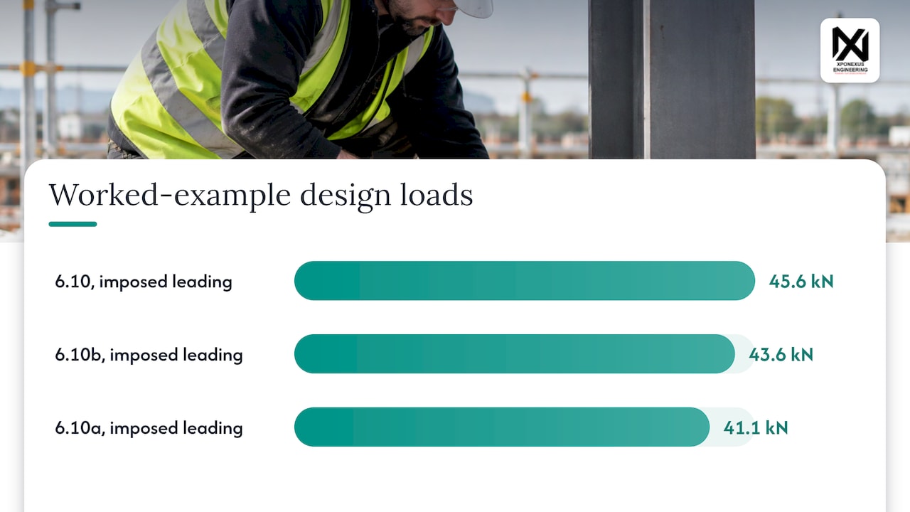
1.35 × 20 + 1.50 × 10 + 1.50 × 0.6 × 4 = 27 + 15 + 3.6 = 45.6 kN
Expression 6.10, wind leading:
1.35 × 20 + 1.50 × 4 + 1.50 × 0.7 × 10 = 27 + 6 + 10.5 = 43.5 kN
Imposed leading governs at 45.6 kN.
Expression 6.10b, imposed leading:
1.25 × 20 + 1.50 × 10 + 1.50 × 0.6 × 4 = 25 + 15 + 3.6 = 43.6 kN
Expression 6.10a, imposed leading (ψ0 on the leading action):
1.35 × 20 + 1.50 × 0.7 × 10 + 1.50 × 0.6 × 4 = 27 + 10.5 + 3.6 = 41.1 kN
The less favourable of 6.10a and 6.10b is 43.6 kN, about 4% lower than the 6.10 result. Whether that saving is worth the extra combinations is a judgement for the project, and the choice should be stated in the calculation so the checker does not have to guess.
In a real model, you would also apply the combinations to horizontal effects, uplift (where permanent load is favourable and takes a lower factor), and every member group, not just one column.
Accidental, seismic and geotechnical cases
Accidental actions are usually short-duration actions of significant magnitude that are unlikely during the design working life. The accidental combination includes the accidental design value Ad, with ψ1 or ψ2 on the leading variable action and ψ2 on the others.
For accidental and seismic situations, a UK application guide states that action partial factors are 1.0, consistent with the UK National Annex. The expression and the project-specific action rules still need checking, so confirm both against the standard and the National Annex before you rely on them.
For geotechnical design, the same guidance identifies three EN 1990 approaches and reports that the UK National Annex favours Approach 1, with separate calculations using the relevant action-factor sets for geotechnical and structural verification. That is why a foundation can carry different design loads from the column above it. Our notes on how UK engineers apply Eurocode 7 and on EC7 partial factors cover this in more detail.
National Annexes: what can and cannot change
The EU Joint Research Centre handbook explains that National Annexes contain only nationally determined parameters and cannot modify the Eurocode text outside permitted national choices. For a UK practice, that means three things:
- Use the UK National Annex values for γ, ψ and ξ, not the recommended values printed in the base EN 1990 text, unless they match.
- If a project follows a different country’s annex (for example a client abroad), say so explicitly at the start of the calculation.
- When you hand work to another team, tell them which annex edition and which expression (6.10 or 6.10a/b) you are using.
Material codes then take the combined design effect forward. See our guides to Eurocode 3 for UK steel engineers and Eurocode 5 for timber structures for how the checks continue after the loads are set.
Common mistakes that cause rework
- Only one leading action. Running imposed-leading and forgetting wind-leading or snow-leading hides the governing case in some members.
- Applying ψ0 to the leading action in 6.10. It belongs only on accompanying actions in 6.10. In 6.10a it is applied to the leading one too.
- Mixing ULS and SLS loads. Deflection checks use SLS combinations, not factored ULS values.
- Favourable permanent action at 1.35. For uplift and overturning, the favourable permanent action takes a lower factor, and EQU has its own set.
- Undeclared choices. A calculation that does not say which expression and annex it uses forces the checker to rebuild it.
- Structure-wide factors for foundations. Geotechnical checks follow their own approach, as above.
These are the points a checker looks for first, and a short “basis of design” page at the front of the package removes most of the questions. Our piece on why structural checks go beyond beam size covers the wider review picture.
A simple workflow for a combination schedule
- Fix the design situation: persistent, transient, accidental or seismic.
- List actions from EN 1991 with their characteristic values and categories.
- Assign γ, ψ and ξ from the UK National Annex.
- Choose 6.10 or 6.10a/b and state it.
- Generate combinations with each variable action leading in turn.
- Run ULS and SLS sets separately and record the governing case per member.
- Put the schedule, the expression choice and the governing cases in the calculation package.
If you want a quick way to sanity-check hand calcs, our structural and civil engineering calculators are a place to start.
Our perspective on load combinations
Load combinations are where a calculation package either earns trust or loses it. Most reviewer comments we see are not about the arithmetic. They are about unstated choices: which expression, which annex, which action leads.
When we embed engineers into a consultancy’s workflow, we set the basis of design first: the UK National Annex values, the expression choice, the combination schedule and the governing cases per member. Our aim is to deliver review-ready calculations aligned to UK standards and Eurocodes, so your checker can follow the logic without a call.
This is also why embedded support suits overflow work. A combination schedule built once and applied consistently across drawings, models and calculations cuts the back-and-forth that slows a submission, and your firm keeps the client relationship throughout.
Mohammed
Get review-ready calculations without a permanent hire
If your team is stretched on calculations, our engineers work inside your process and produce calculation packages with the combination basis stated up front, to UK standards and Eurocodes. We describe our model as embedded remote capacity with NDA protection and a project kick-off within 48 hours. See remote engineering support for how it works, or structural engineering and reports for the calculation scope.

You can also review a past structural calculation support engagement for a UK consultancy to see how packages are presented.
FAQ
What are the standard Eurocode load factors in the UK?
For ordinary STR checks with unfavourable actions, the UK values are γG,sup = 1.35 for permanent actions and γQ = 1.50 for variable actions. In expression 6.10b the permanent factor is reduced to 1.25 through ξ = 0.925. Favourable variable actions are taken as zero.
Should I use 6.10 or 6.10a and 6.10b?
The UK National Annex permits either 6.10 or the less favourable of 6.10a and 6.10b for buildings. 6.10 is simpler and slightly more conservative in many cases. 6.10a/b can reduce the design load but needs more combinations. State your choice in the calculation.
What is the difference between ULS and SLS combinations?
ULS combinations check safety against failure and use partial factors on actions. SLS combinations check behaviour in use, such as deflection and cracking, and do not use the ULS partial factors. Always size and check each against its own set.
Do I need to make every variable action the leading action?
Yes. Each plausible variable action should take a turn as the leading action, with the others reduced by ψ0. The combination producing the most adverse effect on the member or connection governs.
Sources
- EN 1990:2002 Load Combinations, SkyCiv
- BS EN 1991-1-1:2002 Actions on structures
- Steel Building Design: Worked examples for students
- What Are Load Combinations And How To Calculate Them?
- Partial factors: obscure objects of desire?, New Steel Construction
- Application of Load Combinations for Buildings (EN 1990)
- Basis of structural design, JRC Eurocodes handbook
- Manual J calculation
Leave a Reply