

Use the IStructE Standard Method of Detailing Structural Concrete alongside Eurocode 2 clauses on anchorage, laps and cover, backed by BS 4449, BS 8666 and CARES certification. The immediate task for any detailer is to make sure drawings show nominal cover, bar marks with shape codes, lap and anchorage lengths, and pour identifiers before issue. The sections below cover the governing rules, element-specific notes, and a coordination checklist you can apply directly.
TL;DR:
- Most drawing queries stem from incorrect cover, spacing, or anchorage lengths, which can be avoided by applying the correct design values and minimum clear distances as per Eurocode 2.
- Lap and anchorage lengths must be calculated based on bond stress, bar diameter, and the application of alpha factors, with laps staggered when over half the bars are lapped at one point.
- Element-specific detailing requires clear instructions on bar placement, confinement, and support details for slabs, beams, columns, and foundations to prevent on-site errors.
- Coordination of pour sequences and backpropping effects with the contractor is crucial to prevent reinforcement rework and site delays.
- Reinforcement drawings should include all standard references, bar marks, lap locations, pour identifiers, and inspection points to ensure clarity and facilitate quality control.
Table of Contents
- Key detailing rules: cover, spacing, anchorage and lap lengths
- Element-specific detailing notes for slabs, beams, columns and foundations
- Coordination, constructability and contractor detailing
- Checklist and what to show on reinforcement drawings and schedules
- Practitioner perspective: common pitfalls and pragmatic trade-offs
- Xponexus Engineering: reinforcement detailing and embedded engineering support
- Sources
- FAQ
Key detailing rules: cover, spacing, anchorage and lap lengths
Cover, spacing and anchorage are where most drawing queries originate, and getting the numbers right the first time avoids costly re-issues. Nominal cover depends on exposure class and fire requirement, and should always be shown as the design value plus an allowance for deviation, denoted cdev, rather than a single bare figure. Spacing follows a simple rule: the minimum clear distance between bars is the greater of the aggregate size plus 5 millimetres, the bar diameter, or 20 millimetres, as set out in Eurocode 2’s detailing clauses.
Working through anchorage and laps, a detailer typically follows this sequence:
- Calculate the design bond stress, fbd, from the concrete strength class and bar surface condition.
- Derive the basic anchorage length, lb,req, from bar diameter and stress to be anchored.
- Apply the α factors for bar shape, cover and confinement to get the design anchorage length, lbd, checking it against the code minimum.
- Set lap lengths from the same base calculation, staggering laps where more than half the bars in a section are lapped at one point.
- Add transverse reinforcement across laps for large-diameter bars, as required by the code.
- Apply the curtailment shift rule, moving the theoretical cut-off point by an amount related to the effective depth, before showing the bar on the drawing.
Eurocode 2 sets out the full method for these calculations, including the α factors and minimum limits for lbd and lap lengths, alongside the spacing minima detailer reference every day. These figures turn a design calculation into a dimension a steel fixer can follow on site.
Punching shear needs its own attention on the drawing: where links or shear studs are required around a column head or pile cap, show the perimeter, spacing and extent clearly, since this is one of the most common sources of missed reinforcement on site.

Element-specific detailing notes for slabs, beams, columns and foundations
General rules only become useful once translated into element-specific instructions, so each type of member needs its own drawing conventions.
- Slabs need to pour layouts showing which bars belong to which pour, clear location of projecting bars at construction joints, distribution steel spacing, and a distinct plan for punching shear reinforcement around columns.
- Beams require main bar layouts referenced to a link schedule, anchorage details at supports drawn to scale, and curtailment points marked with bar marks rather than left to inference.
- Columns and walls need confinement link or tie spacing stated explicitly, continuity details at construction joints, and starter bar positions coordinated with the foundation below.
- Foundations and pile caps should show bar projections, coupler positions where used, and any handling or transport constraints that affect cage size.
- Prestressed and precast elements need tendon access points, anti-bursting reinforcement at anchorages, stressing pocket details, and notes on transport and handling sequences that affect temporary reinforcement.
Continuity strips and pull-out bars deserve particular care: they are often shown generically on general arrangement drawings, but where they affect construction sequencing they should carry CARES technical approval notes and clear installation tolerances to avoid rework once the strip is cast in.
Coordination, constructability and contractor detailing
Most reinforcement problems on site trace back to a coordination gap rather than a calculation error. Backpropping and preload effects are a common culprit: uncontrolled preload in backprops changes slab load distribution during construction, so the detailer and temporary works designer need to agree the pour and strike sequence before steel is fixed, not after.
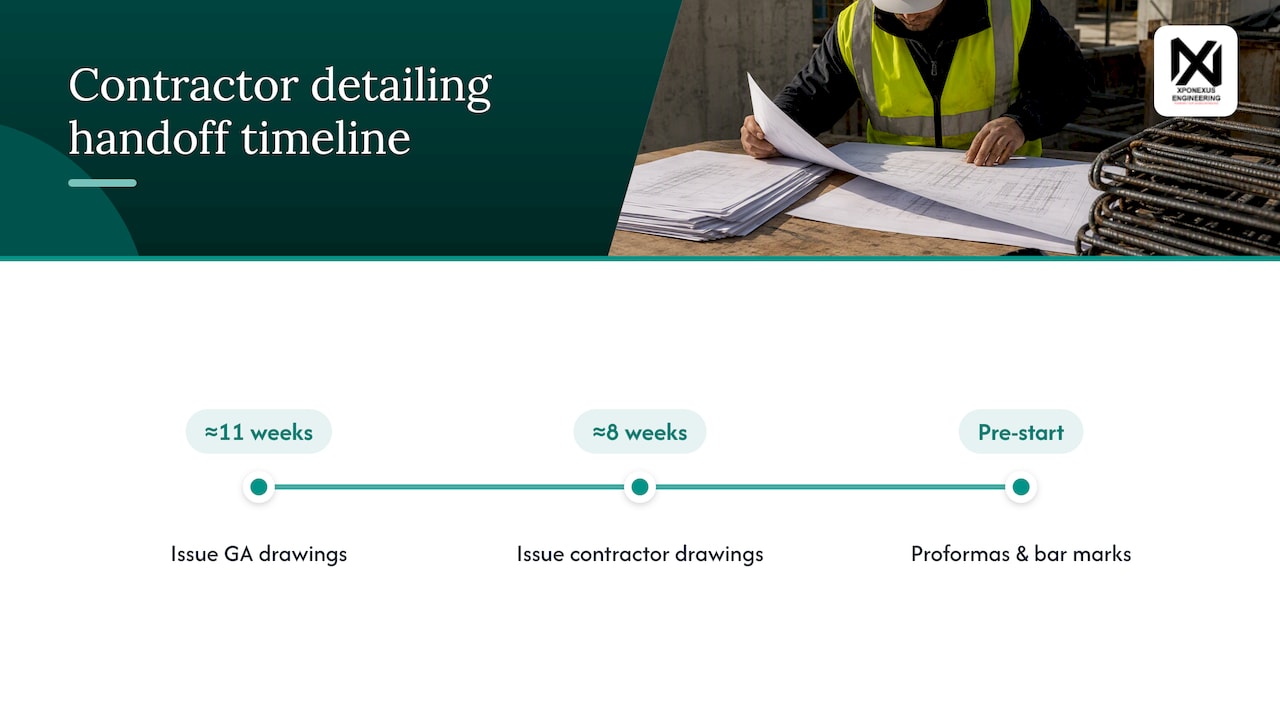
Contractor detailing guidance sets out what needs to change hands and when. CONSTRUCT’s guide to contractor detailing recommends general arrangement drawings be issued around 11 weeks before construction and contractor drawings around 8 weeks before, with proformas and rationalised bar marks reducing queries during fabrication.
BIM and 3D detailing add real value here, particularly for clash detection and automatic schedule exports, though model data still needs checking against fabrication limits before it reaches the yard. Smaller bars at closer centres often ease handling and reduce propping loads, and prefabricated cages can cut site time considerably, provided the drawing states handling weights and lifting points.
Pro Tip: Agree the pour sequence and backprop strike times with the contractor before finalising bar curtailment, since a late change to either can force a full re-detail of the slab.
Checklist and what to show on reinforcement drawings and schedules
A drawing is only as good as the information it forces someone else to find elsewhere. At minimum, every reinforcement drawing should state the reference standards, nominal cover, bar marks with BS 8666 shape codes, lap locations, hook types, coupler positions and pour identifiers.
- Reference standards and design code clauses used for the element.
- Nominal cover with the deviation allowance shown separately.
- Bar marks tied to BS 8666 shape codes, with lap and anchorage lengths dimensioned.
- Pour boundaries, construction joint locations and coupler or continuity strip positions.
| Schedule field | What it must record |
|---|---|
| Bar mark | Unique reference matching the drawing |
| Shape code | BS 8666 code and bending dimensions |
| Quantity and length | Number of bars and cut length per mark |
| Weight | Calculated bar weight for handling and transport |
| Fabrication tolerance | Acceptance criteria for bent and cut steel |
QA entries should record the supplier’s CARES certificate reference and the inspection points at which cover and fixing are checked before pour, giving the site team a short sign-off checklist ready for the drawing register.
Practitioner perspective: common pitfalls and pragmatic trade-offs
The recurring failures are rarely exotic: cover notes left ambiguous, pour sequencing assumed rather than agreed, laps clustered where they should be staggered. Embedding an experienced detailer into a live workflow catches these before issue rather than after a site query, which is where review cycles genuinely shorten. Readers weighing this trade-off may find it useful to see a sample detailing deliverable before committing to a scope.
— Mohammed
Xponexus Engineering: reinforcement detailing and embedded engineering support
Getting reinforcement detailing right on every drawing takes time most consultancies would rather spend on design, not on chasing bar marks and lap notes across a schedule. Xponexus Engineering embeds qualified structural engineers directly into a firm’s workflow to handle reinforcement (rebar) detailing, CAD and BIM outputs, and the wider calculation package, all aligned to Eurocode 2 and UK standards.

- Reinforcement detailing, CAD/BIM modelling and review-ready schedules produced to standards aligned with UK codes and industry best practices.
- Project kick-off typically within a short timeframe, with appropriate confidentiality agreements covering engagements.
- Firms keep control of their client relationships while adding detailing capacity without permanent hires.
For consultancies needing outsourced detailing capacity or a scoped engagement, remote engineering support is the starting point for a sample package or a project-based quote.
Sources
Every reinforcement drawing rests on a small set of documents, and knowing which one governs which decision saves time at review stage. The IStructE Standard method of detailing structural concrete (fourth edition, 2021) is the primary UK detailing manual, offering model details and checklists aligned to Eurocode 2. It was the first update in fifteen years and introduced many new model details, updated throughout to reference BS 8666:2020.
Eurocode 2 (BS EN 1992) sits underneath this manual as the design code: its clauses set the anchorage, lap, spacing and reinforcement minima and maxima that the drawing must reflect. BS 4449 governs the reinforcement itself, BS 8666 governs cutting and bending shape codes, and CARES specification guidance confirms that suppliers should hold product conformity certificates, often needing UKAS Category 2 accreditation for third-party certification.
Beyond these, two pieces of industry guidance shape day-to-day practice:
- The Concrete Centre: Detailing (Eurocode 2)
- CONSTRUCT: A guide to contractor detailing of reinforcement in concrete
Together, these documents answer almost every question a detailer will face on a live project, from bar shape to lap position.
FAQ
What is rebar detailing?
Rebar detailing is the process of turning a structural engineer’s reinforcement design into drawings and schedules that state bar marks, shape codes, cover, laps and anchorage lengths for fabrication and fixing. It follows the IStructE Standard method of detailing structural concrete and is cut and bent to BS 8666 shape codes.
Is GFRP stronger than concrete?
Glass fibre reinforced polymer and concrete are not directly comparable since one is a reinforcement material and the other a structural material they combine with; GFRP bars offer high tensile strength and resist corrosion in ways steel reinforcement does not. Reinforced concrete detailing for GFRP still follows separate design guidance rather than standard Eurocode 2 steel reinforcement rules.
What is the standard method for detailing structural concrete?
The standard method is set out in the IStructE’s Standard method of detailing structural concrete, now in its fourth edition, which provides model details, checklists and drawing presentation guidance aligned to Eurocode 2. It shifts emphasis toward communicating the designer’s intent clearly, so detailers can apply consistent shape codes and schedule formats across a project.
What are the common problems with reinforced concrete?
Common detailing problems include ambiguous cover notes, unstaggered laps, missed transverse reinforcement at large-bar laps, and pour sequences that were never agreed with the contractor. Coordination guidance from CONSTRUCT points to early handover of general arrangement drawings and clear proformas as the main way to reduce these queries before fabrication.
Leave a Reply