

A UK pavement is built from a stack of layers: surface course, binder course, base, sub-base, an optional capping layer and the subgrade (the natural ground) beneath. Each layer spreads vehicle load so the stress reaching the ground is low enough to prevent deformation. That is the principle the Institution of Civil Engineers describes. The thickness of each layer is not a rule of thumb. It follows from design traffic, subgrade strength and drainage, using the Design Manual for Roads and Bridges (DMRB) for the strategic network and local authority standards for most other streets.
This guide walks through the layers from top to bottom, explains how thicknesses are set, and shows where drawings, calculations and drainage design need to line up on a real project.
TL;DR
- A typical flexible UK pavement runs from surface course and binder course, through base and sub-base, to the subgrade, with capping added where the ground is weak.
- Design traffic (in million standard axles), subgrade stiffness or CBR, and drainage drive layer thickness.
- For motorways and trunk roads, CD 226 covers new pavement construction and CD 225 covers foundations. Local authorities often publish their own foundation standards.
- Weak subgrades call for stabilisation, replacement fill or sub-soil drainage, decided from site investigation, not assumption.
- Pavement, drainage and levels are one coordinated package, so the drawings and calculations need to agree before issue.
Table of Contents
- The layers of a UK road pavement, top to bottom
- Flexible, flexible composite and rigid pavements
- What sets the thickness of each layer
- From traffic to a layer thickness: how the design runs
- When the ground is weak
- Which standard applies to your project
- Common coordination problems on pavement packages
- Perspective
- Getting support on civil packages
- Checklist before you issue a pavement package
- FAQ
- Sources
The layers of a UK road pavement, top to bottom
The names below are the ones you will see on UK drawings and in the Manual of Contract Documents for Highway Works (MCHW). Which layers you actually have depends on the pavement type and the traffic it carries.
| Layer | Role | Typical materials |
|---|---|---|
| Surface course | Running surface, texture, waterproofing the layers below | Hot rolled asphalt, thin surface course systems, stone mastic asphalt, macadam |
| Binder course | Load-bearing, regulates levels beneath the surface | Dense bitumen macadam or asphalt binder |
| Base | Main structural layer of the bound pavement | Dense bitumen macadam, higher stiffness bases, cement bound material in composite designs |
| Sub-base | Part of the foundation, working platform for construction | Crushed rock, other granular or bound materials |
| Capping | Improves weak subgrade, where needed | Granular fill or stabilised soil |
| Subgrade | The natural ground that carries everything | Existing soil, assessed by stiffness or CBR |
A useful way to read this table is in two halves. The upper layers (surface, binder, base) are the bound pavement. The sub-base and capping together form the pavement foundation. A local authority specification, Southwark’s DS.602, states that foundations comprise the sub-base and, where necessary, a capping layer.
Surface course
The surface course is what drivers and pedestrians see. It provides a fairly regular running surface and keeps water out of the structure. For macadam surfacing the aggregate is small and hard, usually 6 mm or 10 mm, bound in bitumen. On a highway scheme the surface course is specified through MCHW clauses, so the designer names the material type and thickness and the contractor builds to the clause.
Binder course
Below the surface sits the binder course, or sometimes more than one. It carries load and gives a regular platform for the surface to be laid on. On residential and light-traffic streets, a surface plus binder course on a granular sub-base can be the whole bound structure. On busier roads there is a thicker base beneath.
Base
In the DMRB, flexible pavements have a lower base layer containing asphalt or a hydraulically bound mixture, while rigid pavements are concrete. Stiffer base materials can reduce thickness: the older HD 26 guidance notes that a high modulus base (HMB35) is stiffer than dense bitumen macadam and can give the same life with a thinner base. That matters where construction depth is restricted, for example over services or at tie-ins to existing levels.
Sub-base and capping
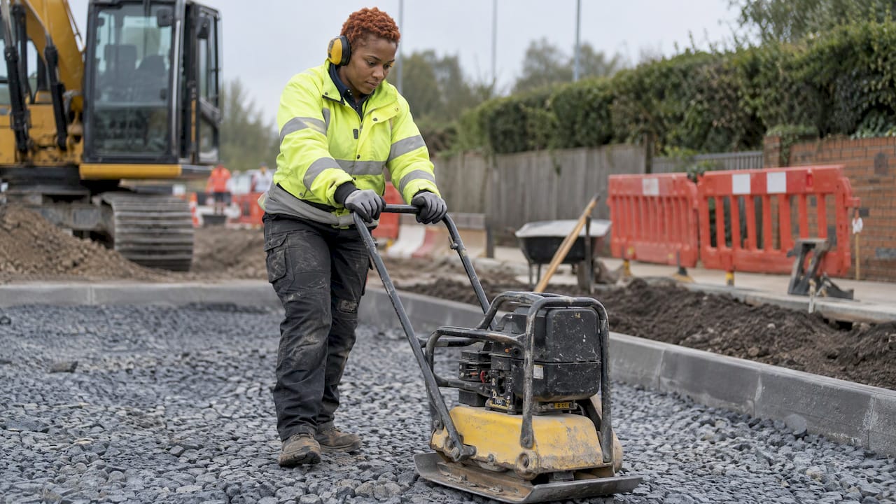
The sub-base is usually crushed rock and does two jobs. It supports the layers above in service, and it gives construction traffic a platform to work from. Capping is added only where the subgrade is too weak for the sub-base alone to do that job. Both are designed under CD 225 on trunk roads, which sets out the design procedure for foundations in terms of resisting loads during construction and over the service life.
Subgrade
The subgrade is the ground you are given. You cannot choose it, only measure it and design around it. That makes site investigation the most important input in the whole process. Southwark’s specification is explicit that site investigations must establish the design subgrade stiffness modulus and form the basis of design.
Flexible, flexible composite and rigid pavements
The layer stack changes with pavement type. The main types you will meet in UK practice are:
- Flexible: bitumen-bound layers over a granular or bound foundation. Most local roads, car parks and access roads are in this family.
- Flexible composite: a bitumen-bound upper layer on a lower base of cement bound material, with transverse cracks typically induced in the cement bound layer. This is described in the HD 26 pavement design section.
- Rigid: concrete slabs. The same source lists unreinforced, jointed reinforced and continuously reinforced types, which rely on slab stiffness to spread traffic loads.
For concrete pavements the reinforcement and joint detailing carry as much weight as the slab depth. If your scheme includes reinforced slabs, our notes on Eurocode 2 checks for reinforced concrete drawings and concrete cover requirements show the kind of detail that avoids rework at review.
What sets the thickness of each layer
Three inputs do most of the work: traffic, subgrade strength and drainage.
Traffic
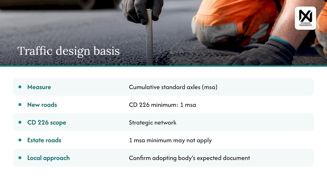
Traffic is expressed as cumulative standard axles, usually in millions (msa). The HD 26 section on pavement design ties heavier traffic to thicker construction. For new roads, CD 226 sets a minimum design traffic of 1 msa, calculated in accordance with CD 224. If you are designing a lightly trafficked estate road or private yard, that minimum does not necessarily apply, because CD 226 is written for the strategic network. Many local authorities set their own approach, so confirm which document the adopting body expects.
Subgrade strength
Subgrade strength is traditionally measured with the California Bearing Ratio (CBR), and it was already a principal factor in total pavement thickness in the old Road Note 29. Current practice leans on stiffness modulus as well as CBR. A weak subgrade does not make the bound layers thicker so much as it demands a better foundation beneath them.
Drainage
Water is the quiet enemy of every layer. The HD 26 section calls for efficient permanent drainage that removes water from the subgrade and any permeable layers. Southwark requires sub-drainage in new streets and spaces, with sub-soil drainage required where the subgrade is weak and groundwater is high. A pavement that sits wet loses stiffness, and no amount of extra asphalt fixes that cheaply.
From traffic to a layer thickness: how the design runs
For a flexible pavement on the strategic network, the sequence is straightforward.
- Find the design traffic. Work out msa over the design life following CD 224.
- Establish the subgrade. Use site investigation to determine design stiffness or CBR.
- Design the foundation. Choose sub-base and any capping under CD 225 to reach the target stiffness.
- Read the pavement thickness. CD 226 uses nomographs relating design traffic to layer thicknesses, with thickness rounded up to the nearest 5 mm.
- Specify materials and levels. Name the materials against MCHW clauses and set design levels from the vertical profile, crossfalls and course thicknesses.
- Coordinate drainage. Confirm sub-surface and surface water routes do not clash with the layer depths.
A worked sense of scale helps. If the subgrade is good, the foundation can be thin and the bound layers carry the traffic. If the subgrade is poor, the first design decision is not the asphalt at all: it is how to bring the foundation up to a usable stiffness.
When the ground is weak
Where subgrade stiffness is below 30 MPa (a CBR below 2.5%), Southwark’s specification offers three improvement routes: in-situ cement or lime stabilisation, replacement with unbound or stabilised granular fill, or sub-soil drainage. Which is right depends on the soil, the groundwater, the programme and what is practical on site.
Two practical points follow from the same document. Subgrades and foundation layers should be protected from trafficking during construction, because a foundation designed for service loads can be wrecked by a wet winter and heavy plant before the asphalt arrives. And foundations are checked not only for the finished road but for the construction phase, which is why the sub-base doubles as a working platform.
Foundations under buildings follow a different logic, but the site investigation habits are shared. Our guides on foundation design reports and shallow foundation bearing capacity explain how ground data should be recorded and issued so the next designer can rely on it.
Which standard applies to your project
The answer depends on who will adopt or own the road.
- Motorways and all-purpose trunk roads: the DMRB. CD 226 sets requirements for new carriageways, widening, upgrading and reconstruction on this network, and MCHW clauses specify materials and construction.
- Local authority streets and spaces: the authority’s own standard, which may reference British and European standards for materials. Southwark’s DS.602 says layer thickness for a given material should not be less than the minimum required by any British or European Standard.
- Private roads, yards and car parks: often designed with DMRB-derived methods or manufacturer guidance, but the client or planning conditions may name a standard.
Early in a project, ask the adopting body which document governs. It is the cheapest way to avoid redesign.
Common coordination problems on pavement packages
Most pavement problems that reach a design review are not about asphalt chemistry. They are about information that does not agree.
- Levels and thicknesses disagree. Design levels are calculated from the vertical profile, crossfalls and course thicknesses, so a change in one layer moves the finished level.
- Drainage clashes with the build-up. Gullies, channels and filter drains need depth, and the pavement foundation needs protecting from water.
- Ground data is out of date. A stiffness value from an early investigation may not match the formation level actually reached.
- Temporary loads are ignored. Cranes, piling rigs and delivery lorries can exceed the design traffic for a short period. Our guidance on temporary works design to BS 5975 covers how to handle those loads properly.
For developments with retaining structures beside the carriageway, the pavement foundation, wall base and drainage all share the same ground. Our reinforced concrete retaining wall project in Bristol shows how that coordination looks in practice.
Perspective
In our experience, pavement packages go wrong at the interfaces, not in the layer table. The asphalt thickness is rarely the problem. The problem is a drainage run drawn at one level, a pavement section drawn at another, and a calculation that assumed a ground stiffness nobody has confirmed.
That is why we embed engineers inside a client’s workflow instead of working from the outside. They produce calculations, drawings and BIM-coordinated models aligned to UK standards and Eurocodes, and they work to the consultancy’s own checking and issue process. The client keeps the relationship with the end customer and the final sign-off.
For a consultancy facing a spike in civil work, the useful question is not whether to hire permanently. It is how fast review-ready information can start moving. We aim to kick off within 48 hours, under NDA, so the design team spends its time on judgement and not on chasing capacity.
Mohammed
Getting support on civil packages
If your consultancy has more civil and structural design than your team can carry, we embed experienced engineers directly into your workflow. They handle calculations, drawings and CAD and BIM coordination, with outputs aligned to UK standards and Eurocodes, and you keep control of the client relationship. Our civil engineering service covers surface water and foul drainage design, the services that sit beside every pavement build-up.

For ongoing overflow capacity, see how remote engineering support works, or contact us via our site to discuss a live project.
Checklist before you issue a pavement package
- The governing standard is confirmed with the adopting body.
- Design traffic is calculated and recorded, with its basis.
- Subgrade stiffness or CBR comes from site investigation and applies to the formation level actually expected.
- Foundation treatment (capping, stabilisation, drainage) is justified for any weak areas.
- Layer thicknesses, materials and MCHW clause references agree between calculations, drawings and specification.
- Design levels reconcile with profile, crossfall and course thicknesses.
- Drainage routes and depths are checked against the build-up.
- Construction-stage trafficking is considered, and the foundation is protected.
A package that ticks these boxes is far easier to review, adopt and build.
FAQ
How many layers does a UK road pavement have?
A typical flexible pavement has at least four: surface course, binder course, sub-base and the subgrade. Busier roads add a structural base, and weak ground may need a capping layer too. The exact number comes from the design traffic and the ground conditions.
What is the difference between sub-base and capping?
The sub-base is the granular or bound layer directly under the bound pavement. Capping is an additional layer beneath it, used only where the subgrade is too weak. Together they make up the pavement foundation, as local standards such as Southwark’s DS.602 describe.
What is a minimum design traffic for new roads in the UK?
For new roads under the DMRB, CD 226 gives a minimum design traffic of 1 msa, calculated in line with CD 224. That applies to the motorway and trunk road network. Other roads follow the adopting authority’s own requirements.
What can be done if the subgrade is weak?
One option is in-situ cement or lime stabilisation. Others are replacement with granular fill or sub-soil drainage. Southwark’s specification treats subgrade stiffness below 30 MPa, a CBR below 2.5%, as the point where these measures come in.
Sources
- Pavement Engineering: Building Roads for the Future, Institution of Civil Engineers
- CD 226 Design for new pavement construction
- CD 225 Design for new pavement foundations
- Structural design of pavement foundation layers, Southwark DS.602
- Section 2, Pavement design and construction, Standards for Highways
- Road Note 29, 3rd edition, TRL
Leave a Reply